As a safety technology that uses the suppression of ignition source energy as an explosion-proof measure, intrinsic safety explosion-proof certification technology has been widely used in engineering projects in various industries due to its advantages of simple structure, small size, light weight, and the ability to maintain, calibrate, and replace parts with electricity.
Basic requirements for circuit design of intrinsic safety explosion-proof
By controlling the electrical parameters of the circuit (such as reducing the parameters of energy storage components such as inductance and capacitance), or reducing the current and voltage of the circuit, the circuit can achieve intrinsic safety and explosion-proof requirements; The components in the circuit should have sufficient power, and the connecting wires should have sufficient cross-section to ensure that the high voltage and current that may be generated under various fault conditions will not damage the performance of the components. The reliability of the circuit is guaranteed through the reliability of the components. This requires the calculation of corresponding electrical component parameters in the intrinsic safety circuit, namely intrinsic safety circuit calculation, to meet the requirements of relevant safety regulations and ensure more secure production. During normal operation, the safety factor is 2.0; When there is a malfunction, the safety factor is 1.5; When there are two faults, the safety factor is 1.0.
The basic principle of intrinsic safety explosion-proof certification technology is to achieve the purpose of explosion prevention by limiting energy. Intrinsic safety technology reliably limits the energy in the circuit within an allowable range under normal or abnormal conditions, to ensure that electrical equipment does not cause explosions of hazardous gases that may exist around it in the event of short circuits, component damage, or other situations.
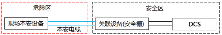
The intrinsic safety explosion-proof system, abbreviated as the intrinsic safety circuit system, consists of three parts: on-site intrinsic safety equipment, intrinsic safety cables, and associated equipment, as shown in Figure 1. The system circuit is divided into intrinsic safety circuits and non intrinsic safety circuits based on safety barriers. The circuit formed by connecting the safety barrier to the field instrument through an intrinsic safety cable is an intrinsic safety circuit; The circuit from the safety barrier to DCS and to the power supply is a non intrinsic safety circuit.
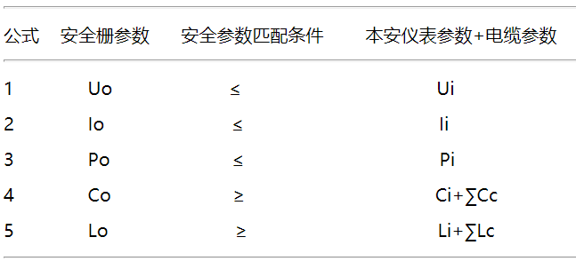
Several inequalities for calculating simple intrinsic safety circuits:
The copyright of this article belongs to Zhongnuo Testing. Plagiarism and theft will be pursued, and reprinting must indicate the original source.
.jpg)

.jpg)
.jpg)
.jpg)
.jpg)

|
||||||
|
||||||